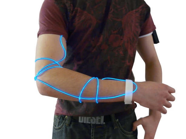
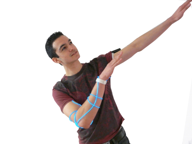
Here’s an image of our Press Release Board aimed at marketing the final product.
Heartbeatz is a revolution in wearable visual dance tech. Utilising Infra-red reflection technology the device detects the heartbeat of its user and mimics the very movement of the blood in your veins with light via a length of Electro Luminescent wire. When listening to a song with a strong, constant bass rhythm the human heart will tune and begin to beat in time with it. The conception of Heartbeatz will allow any onlookers to be able to observe this process. When applied to a large crowd amazing patterns of light can appear throughout a club or event. However, the applications do not end there – Heartbeatz can be utilised in any other situation where a person’s heart rate might want to be observed but in a less formal way, for example keep fit classes, or children playing in the dark.
Heartbeatz is designed to be comfortably wearable using two adjustable Velcro straps to allow any size of arm to wear it. When the unit has been fitted, the wires can be hidden under the clothing with the converter box mounted on the opposite arm via another adjustable Velcro strap – making sure no loose wires are visible.
The heartbeat sensor can be easily and securely fastened onto the pulse of the wearer via a stretchable material that would fasten round the neck to provide the best reading for the unit. However with further advances in this tech it would be possible to mount the sensor almost anywhere on the body, resulting in a more subtle appearance.
Its been a stressful few days. The odds were against us – broken cables, terrible software and even component thieves (yes, some wise guy stole our voltage regulator!). But now… now the prototype is almost finished 😀 That’s right, she lives!
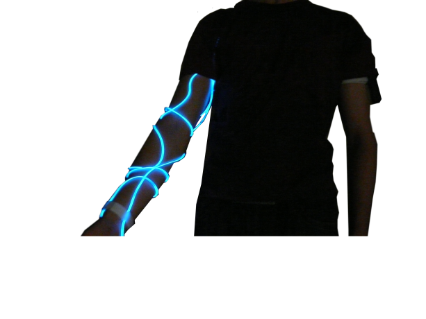
Basically, as your heart beats the wire will light up, depicting the users physical response to different types of music. Check out a video of it working 🙂
Below is a video we shot in the dark without all the masking tape. Works a treat!
More to come soon!
Mike & Allan
There is an electricity in the air inside the studio;
Myself and Mike now have both parts of hardware working to a basic level.
We’ve just hacked our EL device and wired it into a relay to have it driven by the chip.
The final heartbeat sensor hardware is in development.
Now there is just the code – which I’ve had another brainwave on!
More later
Allan & Mike
Some of you might have noticed the blog has been quieter than one of those new fangled electric cars recently.
So I will let you into the loop;
The shape that this project is taking is to illustrate the blood flow through your body – so that the changes to the music can be observed (did you know that your heart “tunes” to a bass beat?). The main piece of tech for this project is being able to measure the heart rate of our test subject.
We’ve been through many prototypes of using different methods, most recently lasers. They have all so far delivered results but none I am happy with.
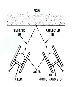
However today we are switching to using infrared diode’s and phototransistors. The theory behind this is that when your blood pumps, the blood vessels under your skin fill with blood, which absorbs some of the IR light – instead of reflecting it. So if the IR emitter is set to reflect off ones skin into a phototransistor – a difference in level can be detected.
From here these readings can be fed into a string of results (or an array) using the PicAxe chip. From here the heartbeat of the subject can be calculated, and any errors can be smoothed or corrected. From this point it is as simple as creating another array that more or less tells the chip how many pulses each “BPM” should have.
From here the chip can operate a relay which will light a length of EL (Elecrto-Luminescant) wire which will be arranged to mimic or simulate the wearers veins. The final design is set to fully cover both lengths of arm – however at this stage the length of one forearm will be used.
Stay tuned!
– Allan
*Copied & Edited from my blog over at Life By Design
After the massive debate a few of us had over who’s better, Yanko Design or JML, I decided to create a poll to end all the arguing. But personally I prefer Yanko.
Feel free to leave comments with your thoughts. To vote just lick on the link bellow. Happy voting 🙂
Mike
Well what can I say; Its been a productive day.
Today Mike and myself set out to create our experimental guitar signal meter.
The day was off to a little bit of a rocky start for a few reasons;
After lugging all the kit – 2 laptops, one guitar + cables, tools, breadboard and electronics and donor material (Marshall amp)
I realised I’d forgotten our multimeter – So theres one trip home.
After returning I thought I’d tune the guitar – and promptly snapped the ‘b’ string. Great
And to top it all off I couldnt source a MOSFET transistor.
But nevermind; we got off to a flying start – Mike researched use of our transistor for amplification while I popped off and unsoldered the Mono Jack we needed to use to accept the guitar input.
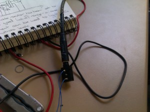
After having this we rechecked the polarity of the signal coming in to the Jack using the multimeter so wires could be soldered and plugged into the appropriate spots on the breadboard.
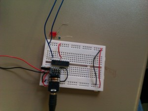
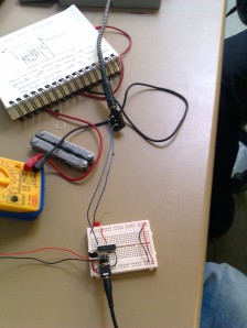
At this point our circuit looked like this:
Now although I predicted that the output signal of the guitar alone would be too weak for the stamp to measure we used the programmers debug command to watch the readings in real time; which yielded some suprising results:
The debug console was showing readable results (although very low) – but still; these readings will do just fine for todays experiment – so we done what any other self respecting designer would do – made a light flash…Just because we could. This concerned programming a simple “If” statement into the stamp – basically saying that if the stamp read anything over a background noise level – to light the Red LED. The results? We’ve got a video for that too!
Now that we are confident we could turn an analog input into a digital output – we set to split the signal into three ranges. Unfortunetly because of the weakness of the signal the ranges would be relatively small and innacurate – but there was a definate proof in the code.
In the end the code that we had looked a little (well, exactly) like this:
 So – There you have it – another successful venture.
Next we will be hunting down and capturing a MOSFET transistor – and amplifying the signal to get a more useful, accurate range out of the signal – then doing something fun with it!
Stay classy internet
– Allan and Mike
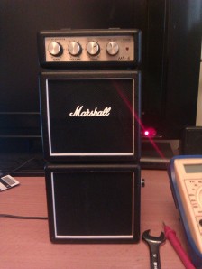
Today I have spent a short amount of time “Device Hacking” Using my Marshall portable double stack amp to conduct some experiments. This is our “test subject” .
After slightly dismanteling the amp to get in at her goodies I was able to start measuring what sort of signal inputs it received from guitars and various audio devices (This will become vital in later work). Firstly measured at the Audio in Jack (without any amplification) I found out that the device was outputting around 100 milivolts upwards (to about 600 milivolts) depending on what was being played on the guitar.
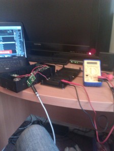
This also told me that as the “Volume” of the playing increased – as did the voltage of the signal – Although this is acctually very hard to tell using a digital mulitmeter. So to test this theory and to build upon our last sort of basic LED circuit – I have began thinking about building a digital LED Signal Volume meter (this will also allow further itteration into a more complete product).
However I am doubtful that the basic stamp can quantify such low input voltage – So I measured what the post amped signal was inside the Marshall – On average between 0v-6v but sometimes beyond – far too high for the stamp.
This gives two options
- Further dismantle my precious marshall amp and retrieve the delicious amplifier circuitry and then provide it with the stamps 5v power supply to give it a more reasonable input
OR
- Design a simple transistor circuit and variable potentiometer to acheive the signal strength needed (and range)
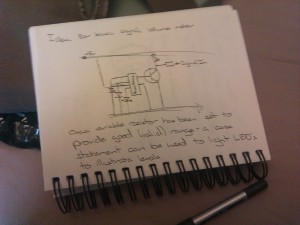
So far I have designed a circuit for the latter as I love my amp too much to harm it further. A basic outline of the circuit and coding is pictured below
And what documentation would be complete without showing the other tool I am using?

Stay tuned to see the finished volume meter
– Allan
Evening all!
Its been an exciting week so far; Taking part in psychological experiments, being a guest on the Pip Carters show, and working PR with my two colleagues (Mike Skillings and David Fisher)
But probably most exciting of all was Tuesdays experimentation class, myself and Mike came up with something tangible by the end of the day. The new program we are using to program the universities new Stamp chips is based on but not a complete replica of the basic language – So is taking some getting to grips with again.
The new stamp chips are particularly interesting because the chip has integrated many features that would usually require additional peripherals such as the ADC (Analog to Digital Converter).
By the end of the day myself and Michael managed to construct the circuit (after some rather fantastic soldering on my part) and code a basic program that would switch on one of two LED’s depending on the value of the attached potentiometer.
Heres a video of the program in action:
Stay tuned for more wacky experiments!
– Allan
